

This guide demonstrates how to read BMS data from Mercedes-Benz EQA, EQB, and EQC modules using the Xhorse Multi-Prog. It covers the wiring connections, chip selection, data reading process, file saving, and the use of ready-made pinouts to make module connection easier and more efficient.
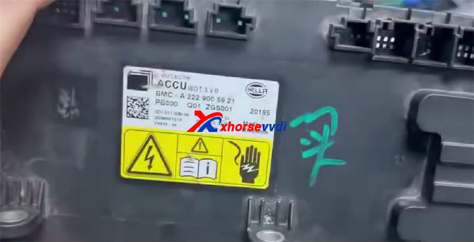
Important Wiring Differences between the Chips
The BMS contains two chips with the same name, but their wiring diagrams are different. For this reason, it is important to identify the correct chip and follow the corresponding connection diagram.
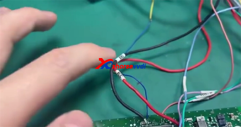
The connection uses several color-coded wires:
- VCC
- GND
- Yellow reset wire
- Green wire
- Blue wires
- Purple wire
- Brown wire on the back of the module
Each wire must be connected to its corresponding position according to the correct wiring diagram.
Step 1: Connect the Module
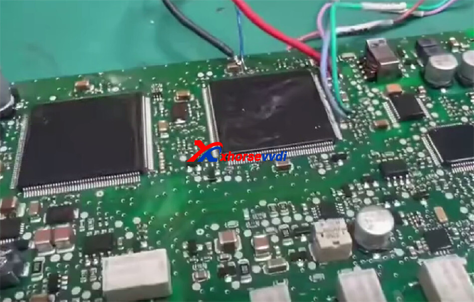
First, connect the front-side wires according to their colors and positions.
The yellow wire is used for reset, while the remaining colored wires are connected to their matching points.
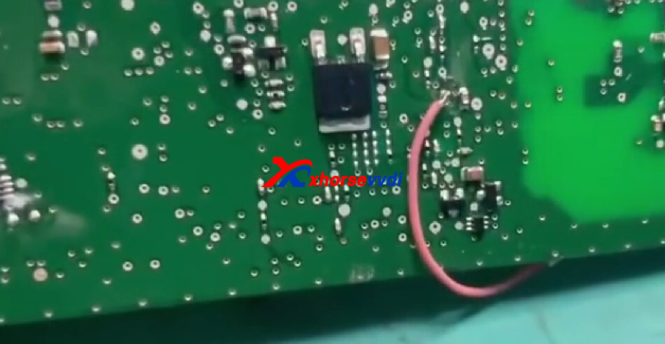
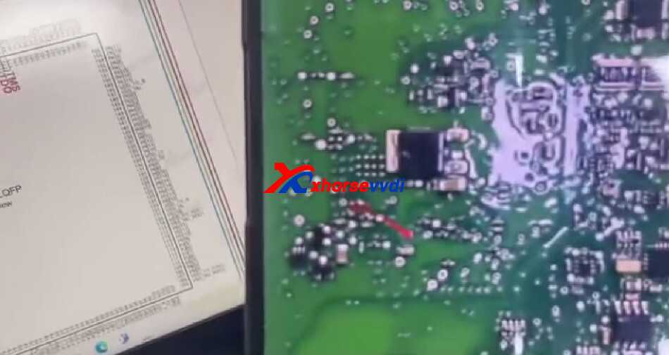
There is also an additional wire on the back of the module.
The brown wire must be connected to the specified position shown in the wiring diagram.
After completing all connections, connect the power supply.
Step 2: Select the Chip in Xhorse Multi Prog
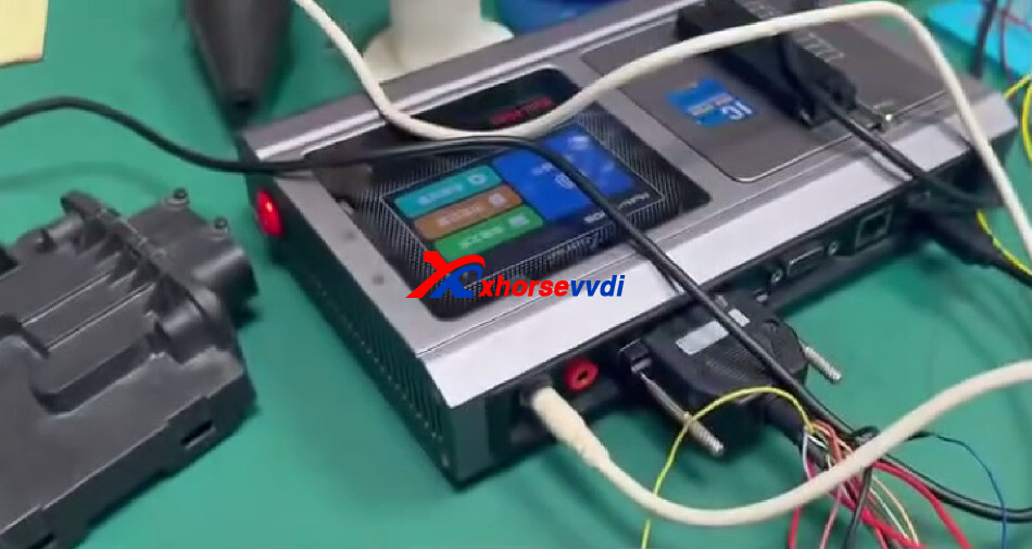
After the hardware connections are complete, return to the computer and open Multi Prog software.
The chip model selected in the demonstration is:
SPC564B74
There are five files in total. The first file is read initially to identify and extract the data.
Step 3: Read the First File
To begin the reading process:
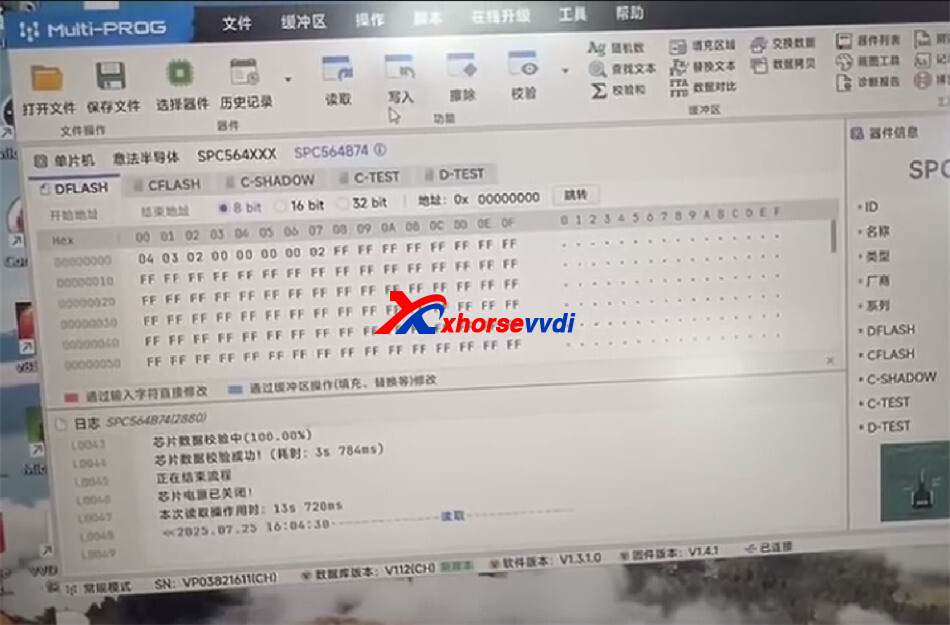
Select the SPC564B74 chip model.
Open the first file.
Start the identification process.
Wait for the software to complete the reading operation.
Check the resulting file after the read is successful.
Once the reading has finished, the extracted data will be displayed in the software.
Step 4: Save the Read Data
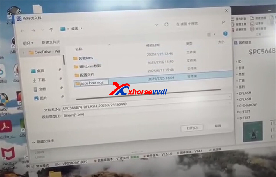
After confirming that the data has been read successfully, save the file properly.
Use the software’s Save function and store the data in the desired location. The demonstration emphasizes saving all extracted data carefully so it can be used later if necessary.
Step 5: Check the Wiring Diagram
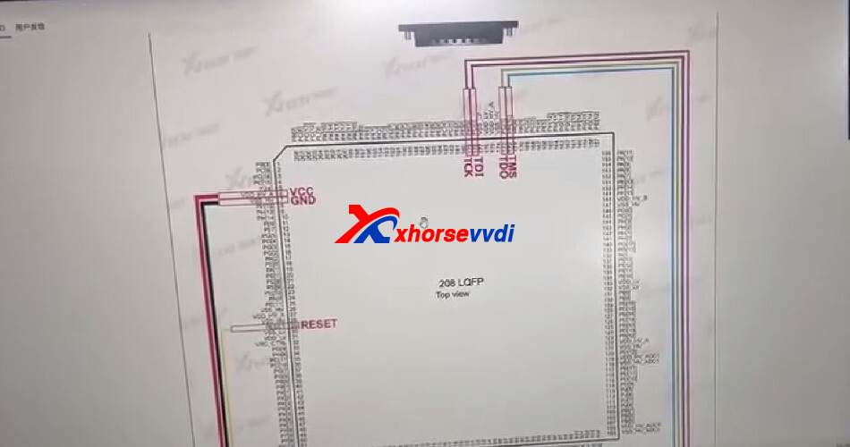
The software also provides a wiring diagram for the chip. Normally, this type of connection must be made directly on the chip.
However, prepared pinouts are available for the modules, making the process easier than connecting directly to individual chip pins.
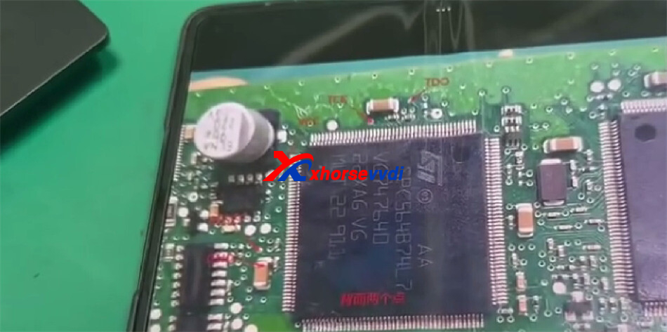
The prepared diagram shows the relevant connection positions, including:
- VCC
- TMS
- TCK
- TDI
Additional connections on the rear side of the module
The TCK connection is located on the back, while TDI and TMS are connected on the indicated side. Because the two chips have different diagrams, always use the diagram that corresponds to the chip being serviced.
Step 6: Read and Write Corrupted Data
BMS data can sometimes become corrupted. In those cases, the programmer can be used to read and write the data.
The demonstrated workflow is:
Connect the BMS according to the correct diagram.
Supply power to the module.
Select the appropriate chip model in Multi–Prog.
Read the available data.
Save the extracted files.
Use the programmer’s read/write functions to address corrupted data when required.
The transcript also notes that solutions are available for repairing corrupted data.
Conclusion
Reading and repairing the BMS modules of Mercedes-Benz EQAE, EQBE, and EQC requires selecting the correct chip type and following its corresponding wiring diagram carefully. With the Xhorse Multi Prog Programmer, BMS data can be read and backed up efficiently, while write operations can be performed when data needs to be restored or corrected. Using the correct module pinout makes the connection easier and more reliable, but it is essential to verify every connection before operation.
Skype: xhorsevvdi.com
Whatsapp: https://wa.me/8613983756354


 Whatsapp:
 Skype: